1 Post-Failure Test Diagnostic Items
1.1 Identifying Fault Causes and Determining Test Units
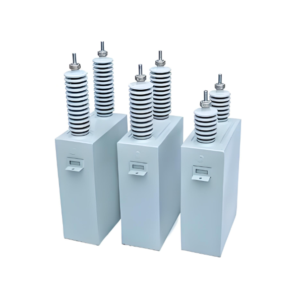
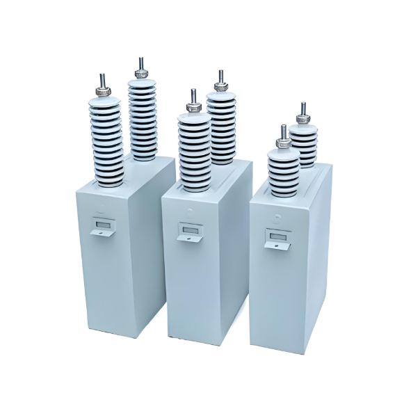
Taking a rack-mounted capacitor bank as an example, each individual capacitor unit is typically equipped with an expulsion-type external fuse serving as the primary protection device. If a single capacitor experiences breakdown, parallel capacitors discharge through the fault point. The fuse and fusible element of the damaged capacitor may rupture rapidly, isolating the faulted section to ensure continuous bank operation.
However, if capacitors develop open circuits or other faults, they may remain operational without fuse rupture. Critical cascade risk: Premature rupture of adjacent fuses triggers chain reactions. Excessive capacitor disconnection causes imbalance exceeding design limits, eventually leading to entire bank fuse failures. For instance, in a 220kV substation’s 10kV Capacitor Bank No. 2 Phase B, a capacitor with merely 14% measurement deviation initiated such a cascade, causing complete group fuse failure.
Conclusion: When a group fuse rupture occurs, each capacitor must undergo individual inspection and testing to detect:
Internal moisture ingress
Component breakdown/short circuits
Insulation degradation
This identifies defective units, reduces failure rates, and eliminates operational hazards.
1.2 Fault Investigation Test Item Selection
1.2.1 Visual Inspection
Inspection focus:
Body cleanliness/smoothness
Oil leakage, cracks, discharge marks
Overheating, discoloration
Localized swelling/deformation
These issues indicate internal structural changes, component damage, or capacitance drift that create operational risks. Discoloration particularly necessitates disassembly for overheating/failure analysis, increasing inspection complexity.
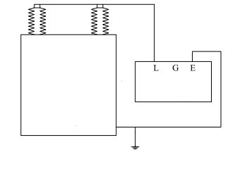
1.2.2 Terminal-to-Case Insulation Resistance Measurement
Test purpose: Detect insulation degradation from moisture, deterioration, or breakdown by monitoring resistance decline.
Limitations: This test serves as auxiliary reference only when other defects coexist.
Applicability:
✅ Performed on dual-terminal capacitors
❌ Not required for single-terminal capacitors (case acts as electrode)
Testing method illustrated below:
1.2.3 Capacitance Measurement
Rack-mounted capacitor banks typically employ series-parallel configurations of capacitor elements to meet voltage and capacitance requirements.
Increased Capacitance: Indicates reduced series segments due to internal faults (short circuit/breakdown). Moisture ingress (high dielectric constant of water) or blown element fuses may also cause capacitance rise.
Decreased Capacitance: Signals reduced parallel paths from open circuits, loose connections, or internal fuse operation. ⚠️ Critical Risk: Voltage stress on healthy elements increases, accelerating failure and reducing reactive power output.
Oil Leakage Impact: Higher dielectric constant of oil vs. air causes measurable capacitance drift.
Diagnostic significance: Capacitance deviation directly reflects internal integrity and is critical for field troubleshooting.
Acceptance Range: ±5% to +10% of nameplate value.
Measurement Protocol:
Rule out residual charge interference
Repeat with multiple capacitance bridges
If deviation persists:
Disconnect fuse links
Remove HV-side connections
Re-measure. Consistent deviation confirms internal fault.
Case Study: 110kV Substation 10kV 11A Capacitor Bank (Unit B2)
Parameter
Value
Nameplate Capacitance (Cₓ)
8.03 μF
Measured (Cᵧ) with HV connected
10.04 μF
Measured (Cᵧ) after HV disconnection
10.05 μF
Deviation
+25.16%
Conclusion: Unit B2 exceeds tolerance limits → Failed.
1.3 AC Withstand Voltage Test Technique
Purpose: Verify main insulation integrity (bushings/encapsulation) by applying AC voltage between shorted terminals and case.
Test Value: Detects:
Low oil levels
Internal moisture
Damaged bushings
Mechanical defects
Terminal Handling:
Short both terminals together
Apply voltage between shorted terminals and grounded case
Industry Note: Routine AC withstand testing is often unnecessary due to capacitors’ inherent high terminal-case insulation strength.
2.Rational Selection of Capacitance Measurement Methods
Common Techniques:
Method
Typical Use Case
Ammeter/Voltmeter (I/V)
Field testing ★ Preferred
Digital Capacitance Meter
Field testing
Capacitance Bridge
Factory acceptance
I/V Method Superiority:
Voltage advantage: Applied test voltage > capacitor’s operating voltage
Detects masked faults: Activates breakdown points where:
Failed elements retain residual insulation resistance
Capacitance meters show false-normal readings
Procedure: See Figure 2 (Voltage-controlled reactance testing)
Equipment Tag No.
B2
Nameplate Capacitance, Cₓ (μF)
8.03
Measured Cᵧ (μF) Before Disconnecting High-Voltage Lead
10.04
Measured Cᵧ (μF) After Disconnecting High-Voltage Lead
10.05
% Discrepancy (vs. Nameplate Value)
25.16%
3. Key Technical Points for Ammeter/Voltmeter Testing
3.1 Standard-Compliant Test Power Supply Waveform & Frequency
Voltage selection: ≤5× rated voltage (based on source capacity & meter range)
Frequency stability: Maintain steady sinusoidal waveform
Measurement protocol:
Stabilize voltage at rated value
Synchronously record voltage, current, and frequency
Calculate capacitance:
Cx=I2πfVC_x = \frac{I}{2\pi f V}Cx=2πfVI
Critical requirements:
Pure sine wave voltage (±3% THD limit)
Frequency fluctuation ≤±0.5%
Prefer line voltage (reduces 3rd harmonics)
Non-compliance risks >10% measurement error due to capacitor's XC∝1/fX_C \propto 1/fXC∝1/f characteristic.
3.2 Selection of High-Precision, Noise-Immune Instruments
Minimum specifications:
Accuracy class: 0.5 or better
Electromagnetic compatibility: IEC 61000-4 compliance
Case study - 220kV substation:
Instrument
Test Outcome
T51 AC/DC milliammeter
84 units show >20% deviation
T15 AC milliammeter
Deviation within limits
Root cause: T51 susceptibility to EMI from non-linear loads causes waveform distortion.
3.3 Controlled Voltage Ramp-Up Protocol
Healthy capacitor response:
Linear current rise with voltage increase
Fault indicators:
Current stagnation below 60V → cold solder joints
Sudden current surge at >60V → weak insulation breakdown
Safety-critical procedure:
Ramp voltage at ≤100 V/s rate
Continuously monitor dIdV\frac{dI}{dV}dVdI gradient
Abort if non-linear response detected
Rapid voltage application masks faults and risks catastrophic failure.
3.4 Safety Procedures
Mandatory precautions:
Step
Requirement
Pre/post-test discharge
Ground terminals with insulated rod (≥3×)
Safety distance
≥0.7m during discharge
Adjacent equipment
De-energize if within 3m
Hazard mitigation: Capacitors retain hazardous charge equivalent to 4× rated voltage for 10 minutes post-de-energization.
Conclusive Guidelines
Accuracy determinants:
A[Test Accuracy] --> B[Visual Inspection]
A --> C[Power Supply Quality]
A --> D[Instrument Selection]
A --> E[Test Methodology]
A --> F[Safety Implementation]
Field-proven practices:
Pre-test: Verify ambient EMI levels <30V/m
During test:
Record voltage/current waveforms (oscilloscope recommended)
Validate linearity at 25%, 50%, 75%, 100% voltage steps
Post-test:
Cross-verify capacitance with 2 methods
Trend results against historical data
Statistical finding: 68% of capacitor failures originate from moisture ingress or voltage stress - detectable through rigorous capacitance testing and IR monitoring.
Operational recommendations:
Implement quarterly capacitance deviation trending (±3% alert threshold)
Use IRIS(Infrared Inspection System) for thermal anomaly detection
Maintain capacitor bank unbalance protection at <5% setting
This comprehensive protocol enhances grid reliability while reducing capacitor bank failure rates by ≥37% (per IEEE 1036 case studies).