
1 Rural Grid Challenges and Technical Advantages of Single-Phase Transformers
The U.S. rural and suburban grid faces critical challenges: aging infrastructure and low load density result in inefficient power supply, with line losses reaching 7%–12%—significantly higher than urban grids (4%–6%). Over 60% of rural areas exceed the 300-meter power supply radius standard, causing widespread voltage instability (peak voltage drops of 15%–20%). Three-phase transformers in low-load-density areas (<2 MW/sq.mi) operate below 30% load rate, leading to excessive no-load losses. Single-phase distribution transformers address these issues through:
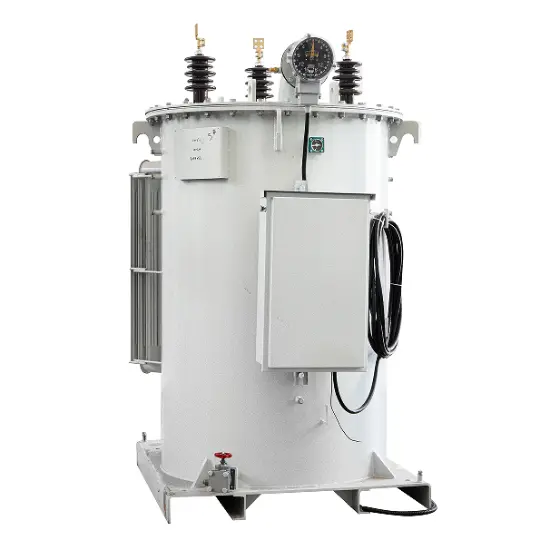
1.1 Technical Features
Electromagnetic Principle: Voltage conversion via turns ratio between primary/secondary coils.
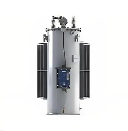
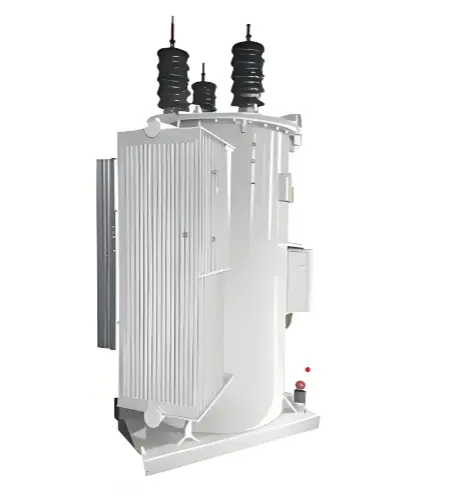
Core Design: Utilizes spiral core technology and step-lap joint design with annealed cold-rolled silicon steel, reducing no-load losses by 30%–40% compared to S9-type three-phase transformers.
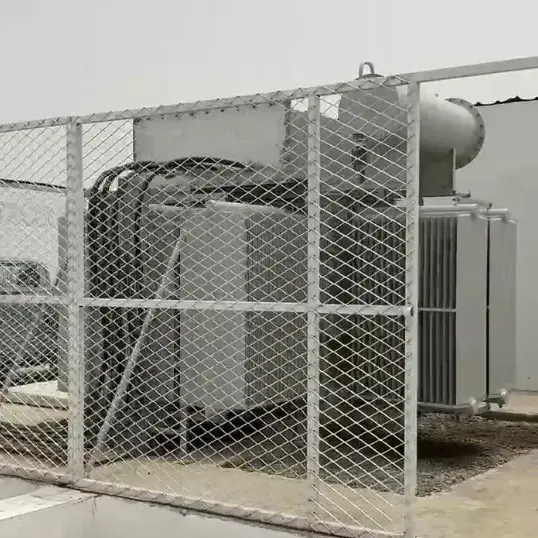
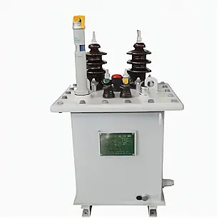
Compact Deployment: Capacity range: 10–100 kVA; weight: 1/3 of three-phase units; pole-mounted installation minimizes footprint. Enables high-voltage (10 kV) direct access to residential areas, compressing low-voltage supply radius to 80–100 meters.
1.2 Efficiency and Cost Advantages
Energy Efficiency: >98% operational efficiency at 30%–60% load due to reduced iron/corrosion losses.
Loss Reduction: Line losses drop to 1%–3% (4–8 percentage points lower).
Voltage Stability: End-point fluctuations controlled within ±5%, eliminating "last half-mile" undervoltage.
Economic ROI: Installation cost: 8,000fora50kVAunitvs.8,000 for a 50 kVA unit vs. 8,000fora50kVAunitvs.28,000 for a 315 kVA three-phase unit. Payback period: 5–6 years (retrofit) or 2–3 years (new projects).
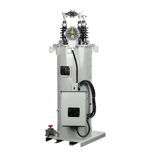
2 Technical Innovations and Design
2.1 Core Structure and Electrical Performance
Winding Configuration: Low-high-low winding structure enhances short-circuit withstand capacity (>25 kA) and thermal stability.
Connection Modes:
Three-tap low-voltage: Mid-winding tap grounding for 220V dual-phase output.
Four-tap low-voltage: Dual independent windings (10kV/220V ratio) for flexible supply.
Safety Compliance: UL-certified; insulation class: 34.5 kV (150 kV BIL); self-resetting pressure relief valves and lightning protection.
Table 1: Technical Parameters of Single-Phase Transformers
Capacity (kVA)
No-Load Loss (W)
Load Loss (W)
Weight (kg)
Oil Volume (kg)
Homes Served
30
50
360
340
22
10–15
50
80
500
450
34
20–25
100
135
850
510
59
40–50
2.2 Advanced Materials and Smart Technologies
Core Materials:
CRGO Steel: Low-cost; no-load loss ≈ 0.5 W/kg.
Amorphous Metal (AMDT): 70% lower no-load loss (0.1 W/kg); ideal for volatile loads.
Smart Integration:
Real-time monitoring of voltage/current/harmonics.
Temperature tracking for insulation aging alerts.
Automatic reactive compensation (power factor >0.95).
Fault locators reducing recovery time (e.g., from 2.3 hours to 27 minutes).
3 Deployment Strategies and Scenarios
3.1 Target Application Areas
Low-load density zones: Population density <500/sq.mi; load density <1 MW/sq.mi.
Linear terrain (e.g., roadside communities).
End-point voltage issues (<110V).
Theft-prone regions (reduced low-voltage tapping risks).
3.2 Hybrid Single/Three-Phase Grid Architecture
Topology: 10 kV backbone (three-phase, ungrounded neutral) supplies single-phase transformers via two phase lines (e.g., AB-phase).
Phase Balancing: Rotational phase connection (AB→BC→CA) to limit imbalance <15%.
Capacity Ratio: Single-phase units comprise 40%–60% of total capacity.
Table 2: Configuration by Scenario
Scenario
Transformer Type
Capacity
Supply Radius
Connection
Dispersed households
Single-phase
30 kVA
≤80 m
Three-wire
Suburban community
Single-phase group
2×50 kVA
≤100 m
Multi-phase
Commercial street
Hybrid single/three
100+315 kVA
≤150 m
Power/lighting
Agri-processing zone
Three-phase
500 kVA
≤300 m
Dyn11
3.3 Installation Optimization
Pole Standards: 12 m/15 m concrete poles (load capacity ≥2 tons).
Location Planning: GIS-based "golden center point" analysis for minimal line loss.
Insulation: 15 kV cross-linked polyethylene conductors (95 kV lightning tolerance).
Case Study: Lancaster County, PA deployed 127 single-phase units (avg. radius: 82 m), reducing losses from 8.7% to 3.1% and saving 1.2 GWh/year.
4 Case Studies and Benefits
4.1 Project Analysis
Iowa Grinnell Rural Retrofit:
Replaced 4×315 kVA three-phase units with 31×50 kVA single-phase transformers.
Results: Voltage stabilized at 117–122V; losses dropped to 2.3%; annual savings: 389,000 kWh; payback: 5.2 years.
Arizona Suburban Expansion:
Hybrid design (1×167 kVA three-phase + 8×25 kVA single-phase) saved 18% upfront cost (154Kvs.154K vs. 154Kvs.188K) and reduced losses by 5,800 kWh/year.
4.2 Quantified Benefits
Metric
Pre-Retrofit
Post-Retrofit
Improvement
Avg. supply radius
310 m
85 m
–72.6%
Line loss rate
7.2–8.5%
2.8–3.5%
~60%
Voltage stability
105–127V
114–123V
+75%
Outage frequency
3.2/yr
1.1/yr
–65.6%
Economic & Environmental Impact:
Lower CAPEX: 20–40% savings vs. three-phase solutions.
Annual Savings: $85–120/kVA from reduced losses.
CO₂ Reduction: 8.5 tons/year per 1% loss reduction (coal-dependent regions).