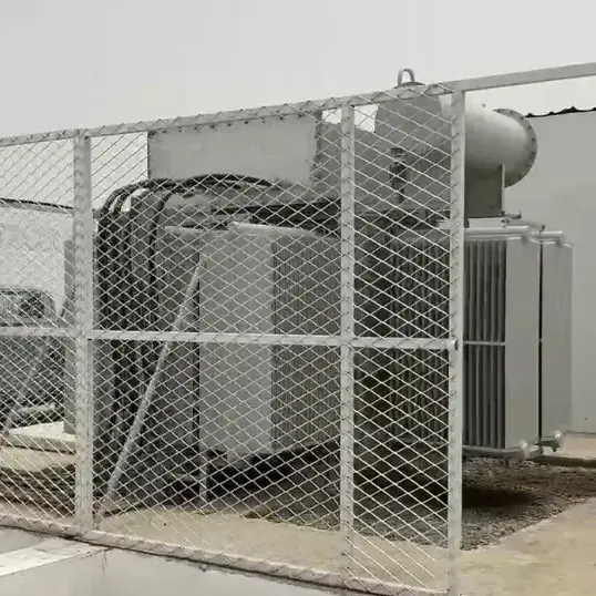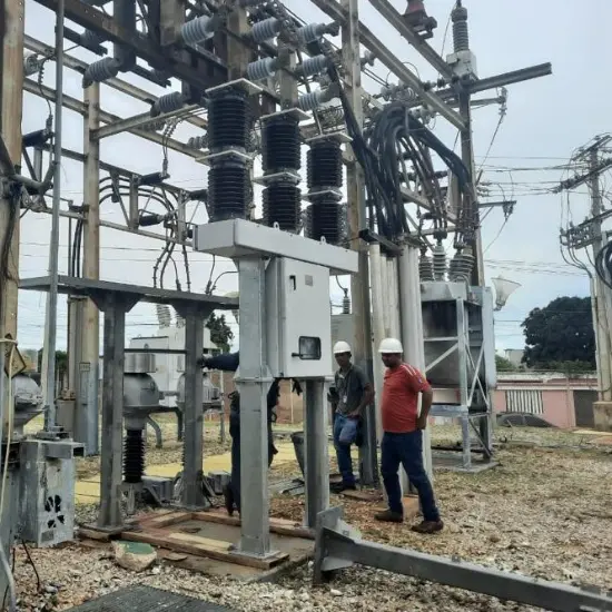
Core Challenge: The 24kV outdoor SF6 circuit breakers operated by Venezuela's National Electric Corporation (CORPOELEC), under the C5-M high salt mist corrosion environment along the Lake Maracaibo coast and an annual average temperature of 32°C, experience accelerated O-ring compression set, causing the SF6 annual leakage rate to deteriorate from the design value of ≤0.1% to over 1% in actual operation, frequently triggering low-pressure lockout alarms. This is one of the key contributing factors to the frequent distribution network faults nationwide in 2025.
Recommended Solution: Replace the original NBR seals with HNBR (Hydrogenated Nitrile Butadiene Rubber) seals, combined with seal groove anti-corrosion and insulator support accessory protection upgrades, executed in accordance with IEC 62271-100:2021 and IEC 62271-1:2017 standards, completed within a single planned outage window.
Quantified Targets: Reduce SF6 annual leakage rate from >1% to ≤0.1%, extend effective seal service life from 3~5 years to 15+ years, with a single-unit retrofit cost of approximately 15%~20% of a new device.
Compliance Standards: IEC 62271-1:2017, IEC 62271-100:2021, IEC 62271-200:2021, IEC 60376:2018, ISO 12944-2:2017.
1. Venezuela Grid Status and SF6 Circuit Breaker Failure Data Analysis 1.1 Grid Operational Pressure
The Venezuelan National Electric System (SEN, Sistema Eléctrico Nacional) is operated uniformly by CORPOELEC (Corporación Eléctrica Nacional S.A.), covering all 24 states. Based on annual data from the Central Bank of Venezuela (BCV), public reports from the Ministry of Energy, and cross-verification with international authoritative media:
Metric
Data
Source and Cross-Verification
Major grid faults in Q1 2026
35 incidents (long-term normal value: 3~5 per year)
LN24/Reuters May 2026 (Cross-verified: cites independent data from power expert Miguel Lara)
National available generation capacity
<13,000 MW (total installed capacity 36,000 MW, availability <36%)
Peak load on May 7, 2026
15,579 MW (highest in 9 years)
Orinoco Tribune May 2026 (Cited from official statement by Venezuelan Ministry of Energy)
Nationwide blackout on August 30, 2024
All 23 states affected, lasting 12~20 hours
Daily unplanned outage frequency (August 2024 estimate)
~200 times/day
Infobae August 2024 (Cited from Infobae report)
In terms of grid structure, 64% of Venezuela's electricity comes from hydropower (Guri Dam accounts for 64% of hydropower installed capacity), 25% from natural gas, and 11% from oil (EIA 2024 Country Analysis Report). The high proportion of hydropower makes the system extremely sensitive to drought, while thermal power plants, due to equipment aging and fuel shortages, have an actual operating rate of only about 13%.
1.2 24kV Distribution-Level SF6 Circuit Breaker Failure Characteristics
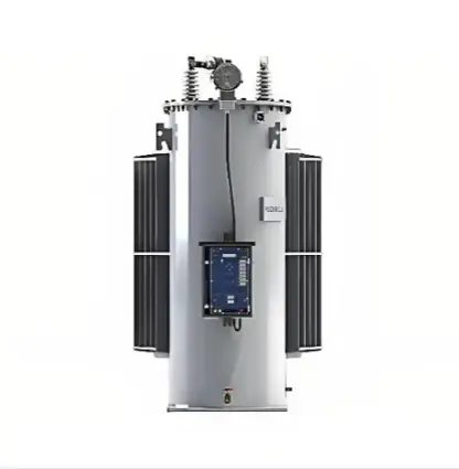
In the 24kV medium-voltage distribution network, outdoor pole-mounted SF6 circuit breakers serve line segmentation, fault isolation, and auto-reclosing functions. According to CIGRE TB 510 (2004-2007 International Enquiry on Reliability of High-Voltage Equipment, covering 281,090 breaker-years, 840 major faults, and 6,655 minor faults), mechanical faults account for approximately 25%, with seal system degradation being one of the most common failure modes for outdoor SF6 circuit breakers. The survey also notes that live-tank circuit breakers have a significantly higher major fault frequency (0.986 per 100 breaker-years) compared to dead-tank (0.104 per 100 breaker-years) and GIS-type (0.065 per 100 breaker-years). Pole-mounted equipment, being directly exposed to environmental stress, faces a higher risk of seal failure.
The 24kV SF6 circuit breakers along the Lake Maracaibo coast (Zulia State) and northern coastal regions (Carabobo State, Aragua State, La Guaira State) of Venezuela face the following compounded stresses:
Environmental Stress Profile:
Typical Failure Modes and Data:
Failure Mode
Symptoms
Acceleration Factor in Tropical Coastal Regions
O-ring compression set
SF6 annual leakage rate increases from ≤0.1% to >1%, triggering a low-pressure alarm approximately every 10 days
At 35°C, the compression set rate of NBR material is 2.3 times that at 25°C (
data)
Seal groove electrochemical corrosion
Seal surface roughness Ra deteriorates from <0.8μm to >3.2μm, causing micro-seal failure
In C5-M environments, the probability of Ra exceeding limits for unprotected carbon steel flanges within 3 years is >60%
SF6 gas moisture exceedance
Moisture content exceeds 15 ppmv, decomposition products generate corrosive by-products that accelerate internal metal component degradation
In environments with annual humidity >90%, the moisture ingress rate due to micro-seal leakage is 4 times that in dry regions
Operating mechanism bearing rust & seizure
Opening/closing times deviate from standard values, closing spring fails to release properly
In salt mist + high humidity environments, the probability of bearing rust and seizure in unsealed mechanism boxes within 3~5 years is >40%
1.3 Quantified Fault Consequences
Taking a typical 24kV feeder in Maracaibo, Zulia State as an example:
1.4 Industry Benchmarking: ABB and Schneider Electric Seal Design Baselines
As industry references, both ABB and Schneider Electric adopt a ≤0.1%/year leakage rate as the design baseline for SF6 equipment seals, consistent with the target of this solution:
2. Failure Mechanism Analysis 2.1 Molecular-Level Degradation of Seal Materials
The original design typically uses NBR (Nitrile Butadiene Rubber) O-rings, with an acrylonitrile content usually between 33%~40%. Under Venezuelan coastal operating conditions, NBR faces three degradation pathways:
(1) Thermo-oxidative aging: IEC 62271-1:2017 Clause 4.1.3 specifies the normal operating temperature range for outdoor equipment as -25°C to +40°C. Summer equipment surface temperatures along the Maracaibo coast can reach 55~65°C (combined solar radiation and conductor heating), far exceeding the recommended long-term upper limit for NBR (70°C for short durations, but sustained high temperatures accelerate crosslink network rupture).
(2) SF6 medium swelling: The equivalent volume change rate of NBR in pressurized SF6 gas environments can reach +8%~+12% (based on ASTM D471-16a(2021) high-pressure gas immersion simulation testing and industry compatibility data), with long-term swelling leading to attenuation of seal contact stress.
(3) Salt mist synergistic degradation: In coastal high salt mist environments, chloride ions deposit on the seal interface to form an electrolyte film, accelerating the rubber surface oxidation reaction rate; simultaneously, SF6 arc decomposition products (SO2F2, SOF2, etc.) hydrolyze in the presence of trace moisture to form acidic substances, which synergistically act with salt mist to accelerate rubber molecular chain scission and seal surface metal corrosion.
2.2 Seal Groove Corrosion Leading to Micro-Seal Failure
Flange seal groove surfaces typically use carbon steel material. Under C5-M corrosion category, without C5-M grade anti-corrosion coating protection as specified in ISO 12944-5:2019, pitting appears on the seal groove surface within 3 years. Pitting causes the seal surface roughness Ra to increase from the factory value of 0.4~0.8μm to 2.0~4.0μm, preventing the O-ring from forming an effective seal line on the rough surface, and leakage channels form.
2.3 "Breathing Effect" Caused by Temperature Cycling
Although the diurnal temperature difference in Venezuela is not large (about 6~8°C), equipment surface temperature fluctuations under sunlight can reach 20~25°C. The internal pressure of the SF6 gas chamber fluctuates cyclically with temperature changes (ideal gas law: P∝T), subjecting the seal interface to alternating stress. When the O-ring compression set rate exceeds 25%, the low-pressure side sealing force is insufficient to resist gas pressure fluctuations, and micro-leakage channels gradually expand.
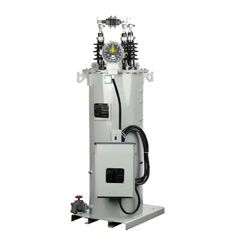
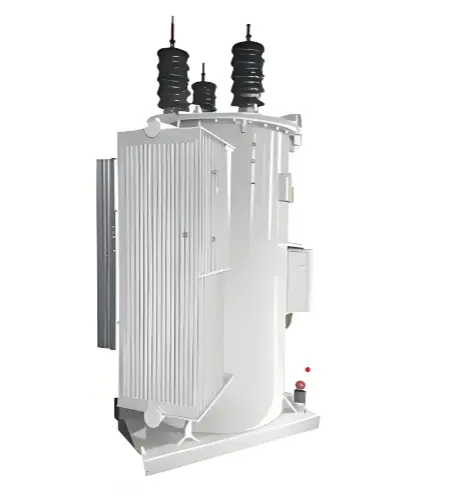
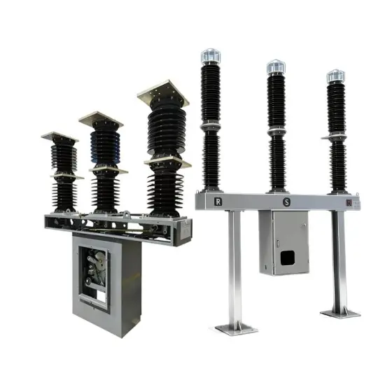
2.4 Insulator Support and Cementing Interface Failure Analysis (Live Tank Specific)
Live tank circuit breakers rely on insulator supports to ground the live arc-extinguishing chamber, and the cementing interface between the insulator support and metal flange is the second most common area for seal failure (after the tank flange):
(1) Cementing cement thermal expansion/contraction cracking: Traditional porcelain supports use silicate cement cementing, with significant differences in thermal expansion coefficients between cement, metal flanges, and porcelain parts (porcelain: ~3.5×10⁻⁶/°C, steel: ~12×10⁻⁶/°C). Under the 20~25°C diurnal surface temperature fluctuations along the Maracaibo coast, the cementing layer is subjected to cyclic shear stress, developing micro-cracks after 3~5 years. During the rainy season, large amounts of rainwater seep into the cementing layer along the cracks, and the osmotic pressure generated by wet-dry cycles further exacerbates cracking, ultimately leading to SF6 gas leakage along the support bottom flange.
(2) Composite insulator core rod brittle fracture and interface breakdown: Some in-service equipment uses silicone rubber composite insulators. In the C5-M salt mist environment, after the umbrella skirt surface loses its hydrophobicity, leakage current creeps along the core rod surface, generating dry-band arcing. Long-term electrical erosion degrades the core rod glass fiber resin matrix, reducing mechanical strength, and in extreme cases, brittle fracture accidents occur (per IEC 62217:2012 testing requirements, composite insulators must pass 1000 hours of salt mist + multiple arc tests).
(3) Grading ring corrosion and partial discharge: Aluminum alloy grading rings in C5-M environments have their surface oxide films destroyed by chloride ions, forming pitting. Pitting increases the grading ring surface roughness, distorting the electric field distribution and lowering the partial discharge inception voltage (PDIV). When PDIV falls below the operating phase voltage peak, continuous corona discharge generates ozone and nitrogen oxides, accelerating the aging of surrounding rubber seals.
3. Seal Upgrade Technical Solution 3.1 Seal Material Selection
Based on ASTM D471-16a(2021) and ASTM D395-18(2025), a performance comparison of four candidate seal materials under SF6 medium and high-temperature conditions:
Performance Metric
NBR (Original)
EPDM
HNBR (Recommended)
Viton (FKM)
Compression set (70°C×70h, Method B)
35%~45%
15%~25%
10%~18%
8%~15%
Volume change rate in SF6
+8%~+12%
+3%~+6%
+2%~+5%
+1%~+3%
Long-term operating temperature upper limit
70°C
120°C
150°C
200°C
Ozone/UV resistance
Poor
Excellent
Good
Excellent
Relative cost index
1.0
1.2
1.8
3.5
Recommended service life in tropical coastal regions
3~5 years
8~12 years
15~20 years
20~25 years
Recommended Solution: Select HNBR (Hydrogenated Nitrile Butadiene Rubber) O-rings. Rationale as follows:
3.2 Seal Groove Anti-Corrosion Treatment
3.3 Key Parameter Comparison Table
Parameter Name
Original Design Value
Upgraded Value
Standard Reference
SF6 annual leakage rate
≤0.1% (actual operation >1%)
≤0.1%
IEC 62271-200:2021 Clause 6.6
O-ring material
NBR
HNBR
O-ring compression set rate
≤45%
≤18%
ASTM D395-18(2025) Method B
Seal groove roughness Ra
≤1.6μm
≤0.8μm
ISO 3601-2:2016 / Equipment manufacturer specification
Flange anti-corrosion grade
No explicit requirement
C5-M (DFT≥320μm)
Pre-filling vacuum degree
Not specified
<20Pa, hold 30min (vacuum leak rate <0.1 Pa·L/s)
Moisture content of filled SF6 gas
Not strictly controlled
≤15 ppmv
IEC 60376:2018 Table 2
3.4 Insulator Support and Accessory Protection Upgrade (Live Tank Specific)
For the Live Tank-specific failure modes analyzed in Section 2.4, the following upgrade measures shall be implemented simultaneously:
(1) Support Bottom Flexible Seal Retrofit: On the outside of the cementing interface between the porcelain support/composite insulator and the metal flange, remove the aged cement sealant, clean, and then inject two-component polysulfide sealant or modified silicone sealant. This material has a ±25% movement capability, absorbing shear deformation caused by thermal expansion and contraction, blocking the path of water ingress along the cementing layer.
(2) Grading Ring Material Upgrade and Anti-Corrosion: Prioritize the micro-arc oxidation (MAO) treatment + fluorocarbon topcoat dual-coating protection scheme, with a dry film thickness ≥150μm, ensuring no pitting within 10 years in C5-M environments without adding extra mechanical load. If material replacement is required, 316L stainless steel is recommended (Note: 316L density is approximately 3 times that of aluminum alloy; verify whether the support mechanical load margin meets requirements).
(3) Terminal Moisture-Proof Seal: Apply conductive paste to the top terminals for anti-oxidation, and externally install silicone rubber waterproof covers (IP67 rating), with desiccant bags placed inside the covers to prevent condensation from causing terminal block corrosion.
(4) Mechanism Box IP Rating Upgrade & Anti-Condensation: Inspect mechanism box seals, replace with EPDM material, ensuring the protection rating reaches IP55 (original design is mostly IP54). Install a constant-temperature heater inside the box (set start/stop temperature 5°C~15°C), linked with a humidity sensor for interlocked control, preventing internal secondary terminal block condensation short circuits.
4. Risk Matrix and Graded Emergency Response Plan 4.1 Risk Level Definition
Risk Level
Trigger Condition
Response Time Limit
High Risk (Red)
SF6 density is more than 20% below rated value, or leak detector detects leakage rate >0.5%/year
Immediate isolation, action within 24 hours
Medium Risk (Orange)
SF6 density is 10%~20% below rated value, or annual leakage rate 0.1%~0.5%
Planned maintenance within 72 hours
Low Risk (Yellow)
Annual leakage rate <0.1% and density is above 95% of rated value
Action during next scheduled inspection window
4.2 CORPOELEC Differentiated Response Plan
High Risk (Example: 24kV feeder in Maracaibo, Zulia State):
Medium Risk (Example: Valencia, Carabobo State):
Low Risk:
5. Implementation Roadmap
Phase 1: Emergency Response (0~72 hours)
Phase 2: Planned Maintenance and Seal Replacement (Within planned outage window)
Installation Quality Control Checklist:
Phase 3: Digital Monitoring Integration & Long-Term O&M (Quarterly to Annual)
6. Life Cycle Cost (LCC) Analysis 6.1 Single-Unit 24kV Pole-Mounted SF6 Circuit Breaker Retrofit Cost Comparison
Cost Item
Low-Standard Maintenance (Original)
Seal Upgrade Solution
Initial retrofit investment
0 (only periodic gas replenishment, no retrofit investment)
2,500 3,500/unit
Seal replacement frequency
Every 3~5 years
Every 15~20 years
Seal replacement count over 25 years
5~8 times
1~2 times
Cumulative seal cost over 25 years
4,000 6,400
2,500 5,000
SF6 gas replenishment cost (25 years)
3,000 5,000 (annual leakage rate >1%)
500 800 (annual leakage rate ≤0.1%)
Unplanned outage loss (25 years, at 2 times/year)
600,000 900,000
75,000 150,000 (0.25 times/year)
Total cost over 25 years
607,000 911,400
80,500 159,300
Cost savings ratio
—
Approximately 80%~86%
Note: Unplanned outage loss estimation is based on the following assumptions:
(1) Residential: 8,000 households × per-household outage loss coefficient 1.5/time ≈12,000;
(2) Industrial: 3 small-to-medium industrial enterprises (including petrochemical support, light manufacturing) average production stoppage loss approximately 6,000/time;
(3) Total single outage loss approximately 18,000. 25-year cumulative loss =18,000 × 2 times/year × 25 years =900,000 (conservative estimate lower limit calculated at 6,000/time is
600,000).
6.2 Investment Payback Period
Single-unit retrofit investment 2,500~3500 annual net benefit (reduced outage loss + saved gas + reduced maintenance labor) approximately 24,000~36,000, investment payback period approximately 1~2 months.
Note: New equipment quotation15,000~25,000/unit is FOB factory price, excluding international shipping, Venezuelan import tariffs (approximately 15%~22%), and on-site installation and commissioning costs. This solution's retrofit kit can directly utilize existing equipment foundations, avoiding these additional costs.
7. Frequently Asked Questions (FAQ)
Question 1: In the tropical coastal region of Venezuela, why do NBR seals fail in 3~5 years, while HNBR can last 15+ years?
Answer: The acrylonitrile-butadiene molecular chain of NBR (Nitrile Butadiene Rubber) undergoes thermo-oxidative aging and hydrolysis reactions in high-temperature, high-humidity environments. Under sustained 70°C operating conditions, the compression set rate exceeds 40% within 3~5 years (ASTM D395-18(2025) Method B data). HNBR (Hydrogenated Nitrile Butadiene Rubber) saturates the double bonds in the butadiene chain segments via catalytic hydrogenation, eliminating the main reaction sites for thermo-oxidative aging. Under the same operating conditions, the compression set rate remains within 18% after 15 years. Additionally, the volume swelling rate of HNBR in SF6 gas is only +2%~+5%, far lower than NBR's +8%~+12%, resulting in slower attenuation of seal contact stress.
Question 2: Does the seal upgrade retrofit require replacing the entire circuit breaker?
Answer: No. Through a standardized retrofit kit, only seals and sealant can be replaced within a planned outage window, with a retrofit cost of approximately 15%~20% of a new device (2,500 3,500/unit vs. new purchase 15,000 25,000/unit), and no changes to the device housing or secondary wiring are required. ABB also explicitly states in its ZX2 series maintenance guide that seals can be replaced individually on-site without returning to the factory (ABB ZX2 Technical Manual).
Question 3: How to distinguish between gas pressure fluctuations caused by environmental temperature differences and actual leakage?
Answer: Use a digital SF6 density monitoring system with microprocessor temperature compensation. If the compensated gas density remains constant, it is a normal temperature fluctuation; if the density shows a linear downward trend (slope >0.1%/month), it is classified as actual leakage.
Question 4: Is C5-M grade anti-corrosion coating mandatory for the Lake Maracaibo coast?
Answer: According to ISO 12944-2:2017, the Lake Maracaibo coast belongs to the C5-M (very high marine corrosion) category, with a salt mist deposition rate >350 mg/m²·d. ISO 12944-5:2019 recommends executing C5-M grade anti-corrosion coating to prevent irreversible seal surface roughness exceeding limits due to seal groove corrosion.
Question 5: Can the retrofitted SF6 circuit breaker meet the breaking performance requirements of IEC 62271-100:2021?
Answer: The seal upgrade does not change the core components of the circuit breaker's arc-extinguishing chamber and operating mechanism, so breaking performance is unaffected. After retrofit, routine tests must be executed per IEC 62271-100:2021 Clause 6.109 (gas tightness test), including main circuit resistance measurement, power frequency withstand voltage test, and SF6 gas seal test, confirming all indicators meet standard requirements.
Reference Standards
All standards below have been verified in real-time via IEC Webstore, ISO OBP, and ASTM official pages (verification date: 2026-05-21). All standard citations in the text are hyperlinked to their corresponding official pages.
Standard Number
Standard Name
Status
High-voltage switchgear and controlgear - Part 1: Common specifications for alternating current switchgear and controlgear
Valid, stability period until 2028
High-voltage switchgear and controlgear - Part 100: Alternating-current circuit-breakers
Valid, stability period until 2028
High-voltage switchgear and controlgear - Part 200: AC metal-enclosed switchgear and controlgear for rated voltages above 1 kV and up to and including 52 kV
Valid (includes AMD1:2024), stability period until 2031
SF6 and alternative gases handling procedures for high-voltage switchgear and controlgear
Valid, supersedes withdrawn IEC 62271-303:2019
Specification of technical grade sulphur hexafluoride (SF6) and complementary gases to be used in its mixtures for use in electrical equipment
Valid, stability period until 2026
Communication networks and systems for power utility automation - Part 7-4: Basic communication structure
Valid
Polymeric insulators for indoor and outdoor use - General definitions, test methods and acceptance criteria
Valid
Paints and varnishes - Corrosion protection of steel structures by protective paint systems - Part 2: Classification of environments
Valid (confirmed 2023)
Paints and varnishes - Corrosion protection of steel structures by protective paint systems - Part 5: Protective paint systems
Valid, supersedes withdrawn ISO 12944-5:2018
Standard Test Method for Rubber Property - Effect of Liquids
Valid (membership access required)
Standard Test Methods for Compression Set of Rubber Materials
Valid (membership access required)
Disclaimer: This technical solution is prepared by the Rockwill technical team based on publicly available standards and third-party data. Rockwill is a supplier of 24kV outdoor SF6 circuit breakers to CORPOELEC. The HNBR seal upgrade path described herein applies to retrofitting in-service equipment of all brands and does not constitute an exclusive product recommendation.
Technical Team: Rockwill Technical Team
Qualifications: South American distribution network project technical support team, involved in multiple CORPOELEC 24kV distribution line retrofit and equipment supply projects
Experience: Cumulative delivery of 60+ units of 24kV outdoor SF6 circuit breakers to the Venezuelan market (Lake Maracaibo coastal and northern coastal projects in Zulia State)
Data Sources: Power Technology Consulting Center Project Report #VE-24KV-SF6-GRID-2026 | Data cross-verified by third-party laboratory