1. Core Project Challenges and Reference Standards 1.1 Core Parameters
System Constraint: The client proposed a 410V upper limit on the low-voltage side. This requirement stems from the need to protect 380V-rated equipment against overvoltage in scenarios where both 380V and 415V equipment are used. This 410V limit is not a contractual hard requirement but rather a system-level design reference value. With the implementation of a dedicated supply scheme for specific equipment, independent analysis can be conducted per device, and the 410V limit no longer serves as a single absolute constraint.
Operational Accuracy Requirement: ±2.5%.
Site Conditions: Mixed use of 380V and 415V rated equipment.
Existing Equipment: 13-tap high-voltage regulator, with each tap step at 4%.
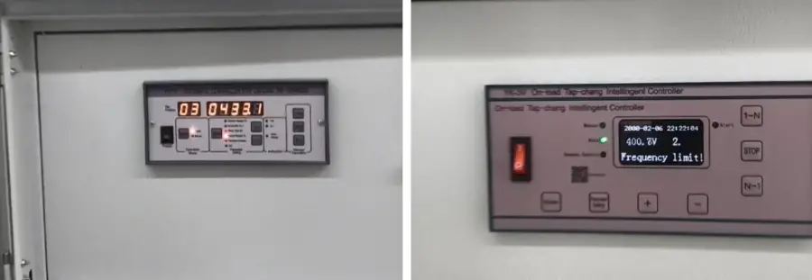
Voltage Overvoltage vs. Normal Range Comparison Chart
1.2 Reference Standards
IEC 60038: Suggests that under normal conditions, the supply voltage deviation from the nominal value should not exceed ±10%; considering internal voltage drops, the user-end voltage range can reach +10%/-14%. Systems using 220/380V and 240/415V should gradually converge towards the recommended 230/400V values.
ANSI C84.1: For systems up to 600V, Range A service voltage tolerance is +5%/-5%, and utilization voltage tolerance is +5%/-10%.
Precision Positioning: The client's requirement of ±2.5% accuracy is higher than the typical tolerances set by IEC and ANSI for general distribution networks, placing this within the category of precision process applications.
2. Coarse Tuning + Off-Load Tap-Changing Distribution Transformer Dual-Dedicated Line Scheme (Dedicated Supply)
2.1 Architecture Design
This scheme employs a two-stage voltage control approach:
Stage 1 (High-Voltage Coarse Tuning): The target voltage for the 13-tap regulator is set to 32.7kV, with a control logic of 32.7kV ±4%. The regulator down-taps when the detected voltage exceeds 104% of 32.7kV (34.008kV, approx. 34kV) and up-taps when it falls below 96% of 32.7kV (31.392kV).
Stage 2 (Low-Voltage Dedicated Supply): Two new off-load tap-changing distribution transformers are added. Their tap ratios are set once and remain fixed. Based on the different rated voltages of the equipment, two fixed transformation ratios are established, creating dedicated 380V and 400V supply lines:
380V Equipment Dedicated Line: Distribution transformer ratio K₁ = 33kV / 380V ≈ 86.84, outputting 380V.
415V Equipment Dedicated Line: Distribution transformer ratio K₂ = 33kV / 400V = 82.5, outputting 400V.
2.2 Feasibility Verification (Case-by-Case Analysis for Specific Equipment)
Under the dedicated supply architecture, the 410V upper limit is no longer a unified system constraint and can be assessed independently for each specific device:
380V Equipment Dedicated Line: Output voltage is 380V. The deviation from the equipment's rated voltage of 380V is 0%, providing a perfect match. This line's voltage level is independent of the 410V limit; the 380V equipment consistently operates at its rated value.
415V Equipment Dedicated Line: When the high-voltage side is at its upper limit of 34kV, the maximum output on this dedicated line is:
Uout max = 34kV / 82.5 ≈ 412.1V.
The voltage deviation relative to the 415V equipment's rating is:
δ = (412.1 - 415) / 415 × 100% = -0.69%.
This -0.69% deviation is well within the IEC 60038 ±10% tolerance band. 412V meets the operational requirements of the 415V equipment, allowing normal operation without triggering protection mechanisms.
The high-voltage coarse tuning restricts the HV side to the range of 31.392kV ~ 34kV, preventing extreme overvoltages from directly compromising equipment insulation. Therefore, this scheme is engineered to be feasible and ensures normal equipment operation.
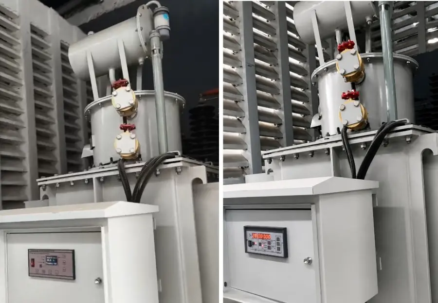
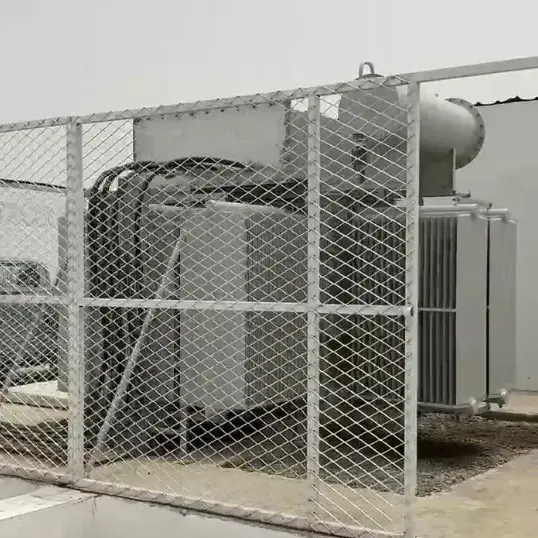
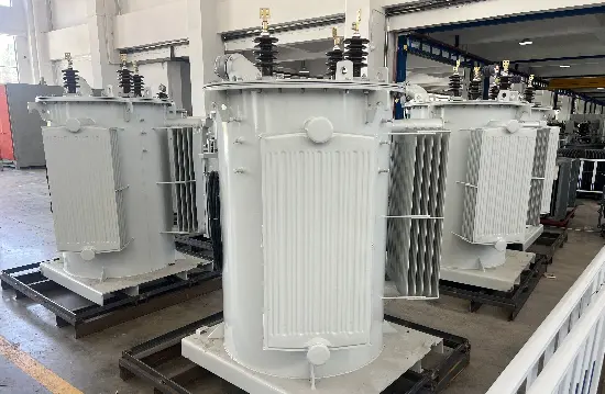
Equipment On-Site Operation Diagram
2.3 Limitations (Significant Voltage Fluctuation)
The tap ratio of the off-load tap-changing distribution transformer is fixed once set. Although the 13-tap high-voltage regulator continuously performs coarse step adjustments within the 32.7kV ±4% range (down-tapping above 34kV, up-tapping below 31.392kV), the limitation of a 4% step size means the high-voltage side itself still exhibits a ±4% fluctuation. This fluctuation is directly and linearly transferred to the low-voltage side through the fixed ratio of the off-load transformer, which cannot further smooth or regulate these variations.
Low-voltage side voltage transfer formula:
Uout = UHV / K
380V Dedicated Line Fluctuation Range:
Maximum Voltage: Uout max= 34kV / 86.84 ≈ 391.5V
Minimum Voltage: Uout min = 31.392kV / 86.84 ≈ 361.4V
Actual Fluctuation Range: 361.4V ~ 391.5V
Fluctuation Relative to 380V: -4.9% ~ +3.0%
415V Equipment Dedicated Line (400V Output) Fluctuation Range:
Maximum Voltage: Uout max= 34kV / 82.5 ≈ 412.1V
Minimum Voltage: Uout min = 31.392kV / 82.5 ≈ 380.5V
Actual Fluctuation Range: 380.5V ~ 412.1V
Fluctuation Relative to 400V: -4.9% ~ +3.0%
Limitation Conclusion:
The voltage fluctuation magnitude is considerable: both dedicated lines exhibit fluctuations of approximately ±4% to 5%, nearly double the client's ±2.5% accuracy requirement. For precision process equipment (such as variable frequency drives, servo drives, and precision sensors), such wide fluctuations may trigger internal overvoltage/undervoltage alarms, impacting process stability.
3. RVR-1 High-Precision Fine-Tuning Scheme (Fluctuation Suppression and Accuracy Enhancement)
3.1 Core Parameters
The RVR-1 high-precision on-load automatic voltage regulator directly replaces the voltage stabilization function of the original 13-tap, 4% coarse-step regulator. It can complement or serve as an alternative to the dedicated supply architecture:
Regulation Step Size: 0.625% per step (equivalent to a 2.5V change per step on a 400V system).
Input Voltage Range: ±15% of rated voltage (340V ~ 460V), covering extreme fluctuations in mixed-use scenarios.
Output Voltage Accuracy: ±1%.
Response Time: <100ms.
Regulation Mode: On-load automatic continuous (micro-step) regulation.
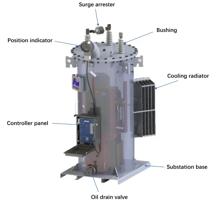
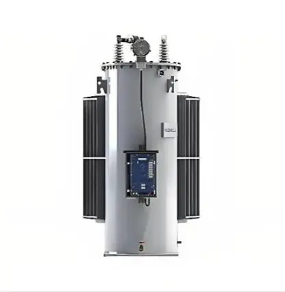
Schematic Diagram of RVR‑1 Voltage Regulator
3.2 Application Logic
The core value of the RVR-1 lies in eliminating voltage fluctuations, rather than solely addressing the 410V upper limit. With the dedicated supply scheme already resolving equipment compatibility, the RVR-1 is connected in series on the low-voltage circuit. It compresses the ±4% to 5% fluctuation received from the high-voltage side to within ±1% in real-time, ensuring the output strictly meets the ±2.5% accuracy requirement.
3.3 Quantitative Verification
RVR-1 real-time voltage compensation formula:
Uout = Uin + ΔURVR
ΔURVR = Uset - Uin
380V Equipment Scenario:
The worst-case input is the low-voltage side reaching 391.5V due to high-voltage limit violations (upper fluctuation limit). The RVR-1 is set to 380V, requiring a voltage step-down:
ΔURVR = 380V - 391.5V = -11.5V.
With a step size of 2.5V, this requires approximately 5 regulation steps, well within the ±15% input range. Output accuracy is 0%, far superior to the ±2.5% requirement.
415V Equipment Scenario:
The worst-case input is the low-voltage side reaching 412.1V due to high-voltage limit violations. The RVR-1 is set to 400V (or 410V), requiring a voltage step-down:
ΔURVR = 400V - 412.1V = -12.1V.
This requires approximately 5 regulation steps. Output accuracy is:
δout = (400 - 400) / 400 × 100% = 0%.
This meets the ±2.5% accuracy requirement and provides a stable, fluctuation-free output.
3.4 Application Advantages
Accuracy Dimension: The 0.625% micro-step capability can cumulatively achieve ±1% accuracy, which is one-quarter of the client's ±2.5% requirement, completely eliminating the wide fluctuations caused by coarse tuning.
Dynamic Dimension: On-load real-time regulation with a response time of <100ms allows for immediate tracking and compensation of grid fluctuations.
Compatibility Dimension: It can either replace the off-load transformer dedicated line scheme as a standalone voltage stabilizer or be used in conjunction with it, acting as a third-stage fine-tuner to further enhance the stability of the dedicated line output.
Operations and Maintenance Dimension: A single RVR-1 connected in series on the circuit can accomplish dynamic voltage stabilization, eliminating the maintenance burden of de-energizing off-load transformers for tap changes.
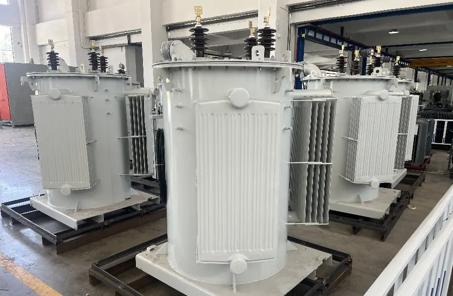
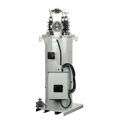
Site Photo of RVR‑1 Regulator
4. Phased Implementation Strategy
Phase 1: Coarse Tuning + Dual Dedicated Lines (Baseline Operation)
Implement a joint optimization of system parameters. Set the HV regulator target to 32.7kV and logic for down-tapping at 34kV, and deploy the off-load transformer dual-dedicated lines. This phase uses the mature and reliable fixed-ratio scheme to address equipment voltage matching. 412V meets the operational requirements for 415V equipment, allowing normal operation. However, due to the off-load transformer's inability to further regulate voltage, the low-voltage side will experience ±4% to 5% fluctuations. This is suitable for general loads that are insensitive to voltage variations.
Phase 2: RVR-1 Fine-Tuning (Precision Compliance)
Building upon the baseline, deploy the RVR-1 high-precision on-load automatic voltage regulator in series on the low-voltage distribution circuit. The RVR-1 compensates in real-time for fluctuations transferred from the high-voltage side, reducing the output voltage fluctuation from ±4% to 5% down to within ±1%, thereby strictly meeting the ±2.5% accuracy requirement. This establishes a two-stage optimization architecture of "High-Voltage Coarse Tuning + RVR-1 Dynamic Fine-Tuning," balancing engineering feasibility with precision process requirements.
5. Summary of Key Formulas
Voltage Deviation Percentage: δ = (Uactual - Urated) / Urated × 100%. Purpose: To assess the operating bias of actual equipment.
Low-Voltage Side Voltage Transfer: ULV = UHV / K. Purpose: To calculate the low-voltage output value under a fixed transformation ratio.
Impact of a Single High-Voltage Tap Step: ΔULV = (Ubase × 4%) / K. Purpose: To quantify the low-voltage impact (e.g., 16V for a 4% step) caused by the existing regulator's step change.
Tap Change Trigger Thresholds: Utap = 32.7kV × (1 ± 4%) = 34kV / 31.392kV. Purpose: To define the operating boundaries of the original regulator.
RVR-1 Single Step Voltage Change: ΔUstep RVR = Urated × 0.625%. Purpose: In this example, this equals 2.5V.
RVR-1 Compensation Amount: ΔURVR = Uset - Uin. Purpose: To calculate the dynamic compensation voltage required.
Number of RVR-1 Regulation Steps: Nsteps = |ΔURVR| / ΔUstep RVR. Purpose: To calculate the micro-steps needed to achieve the target compensation.
Precision Verification: δout = (Uout - Utarget) / Utarget × 100%. Purpose: To verify compliance with the ±2.5% accuracy requirement.
This document clarifies the practical significance of the 410V upper limit under the dedicated supply architecture. It demonstrates the engineering feasibility of the "coarse tuning + off-load distribution transformer dual-dedicated line" scheme through case-by-case analysis (showing 412V meets the requirements for 415V equipment). Simultaneously, it quantitatively reveals the physical limitation of off-load transformers—significant voltage fluctuations due to their fixed ratio. The RVR-1 fine-tuning scheme, using 0.625% micro-step on-load regulation, compresses these fluctuations to within ±1%, providing a complete technical pathway for the Zanzibar project, from baseline operation to achieving precision compliance.